Finalmente, el puente transbordador construido por Ferdinand Arnodin en Ruan, que había servido de inspiración para plantear una opción admisible tanto desde el punto de vista técnico y económico, como para sortear las rígidas exigencias militares, no se llevaría a cabo. Cabe imagnar que el ingeniero municipal Thomas F McGilvray (1860-1959) analizaría la propuesta de Arnodin, que como ya hemos dicho tenía patentado su puente transbordador en los EE.UU. pero, si hemos de creer sus palabras, por razones derivadas de la dureza del clima, de los fuertes vientos y las grandes nevadas y bajas temperaturas invernales, se acabó decantando por la realización de un puente transbordador que no utilizase cables ni en la sujección de la viga superior, ni en la suspensión de la barquilla. La solución finalmente adoptada fue aprobada por el Departamento de Guerra y aceptada también por la población de Duluth; la Asamblea Legislativa del Estado aprobó una emisión de bonos de 100.000 dólares, coste estimado del puente y se elaboró un proyecto que fue licitado en 1901.
En realidad, aunque la idea de la patente de Palacio y Arnodin y la esencia del puente transbordador de Portugalete permanece: una barquilla que se traslada de una orilla a otra suspendida de un carro que discurre por unos carriles instalados en una viga horizontal elevada, las dos modificaciones más patentes introducidas en Duluth son: 1/ la modificación del modo de sustentación de la viga, que en Duluth se apoya directamente sobre las dos torres, y 2/ la sustitución de los cables que soportan la barquilla por una ligera estructura de celosía rígida.
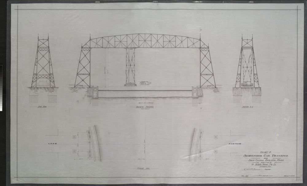
Suspended car transfer over ship canal. Duluth, Minn. 1901 C A P Turner, Engineer. / Minnesota Digital Library
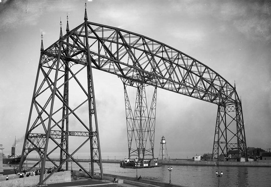
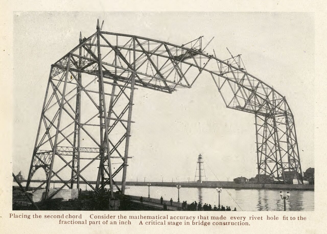
En el plano del proyecto que reproducimos, realizado por el ingeniero Claude A P Turner de la Structural Company, y en las ilustraciones que acompañan esta entrada pueden apreciarse las características de la estructura de celosía finalmente construída; se trata de dos pilas de ancha base, de escasa esbeltez, y una viga de sección variable con cordon superior curvo, de mayor canto en el centro. La barquilla cuelga de una ligera estructura que partiendo de cuatro puntos en la parte superior, se ensancha hasta hacerse solidaria en la parte central, para de nuevo finalizar en cuatro puntos en la sujección de la barquilla. Las únicas concesiones ajenas a lo puramente estructural y más cercanas a la ornamentación serían los pináculos que rematan las pilas-torre y los arcos en el acceso a ambas pilas. En las ilustraciones que nos han llegado de un proyecto inicial de 1901 se aprecia una composición de la celosía de la viga menos racional y una sobreelevación de las torres por encima de la viga.
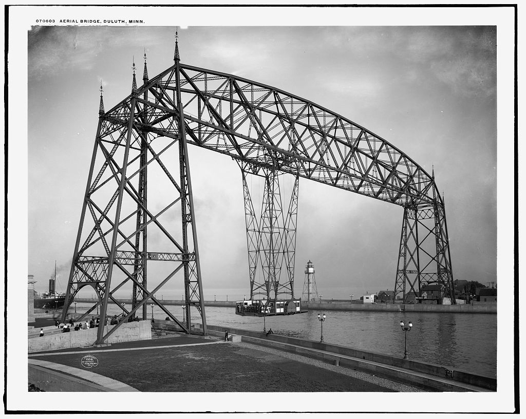
Puente transbordador de Duluth, 1905. / Library of Congress. Estados Unidos.
Aunque se llegaron a construir los estribos del puente, la empresa adjudicataria abandonó las obras que quedaron paralizadas hasta que en 1904 se firmó un nuevo contrato con la Modern Steel Structural Co. de Waukesha, Wisconsin. Las obras del puente realizadas según el proyecto definitivo de Turner se finalizaron en el invierno de 1904-1905.
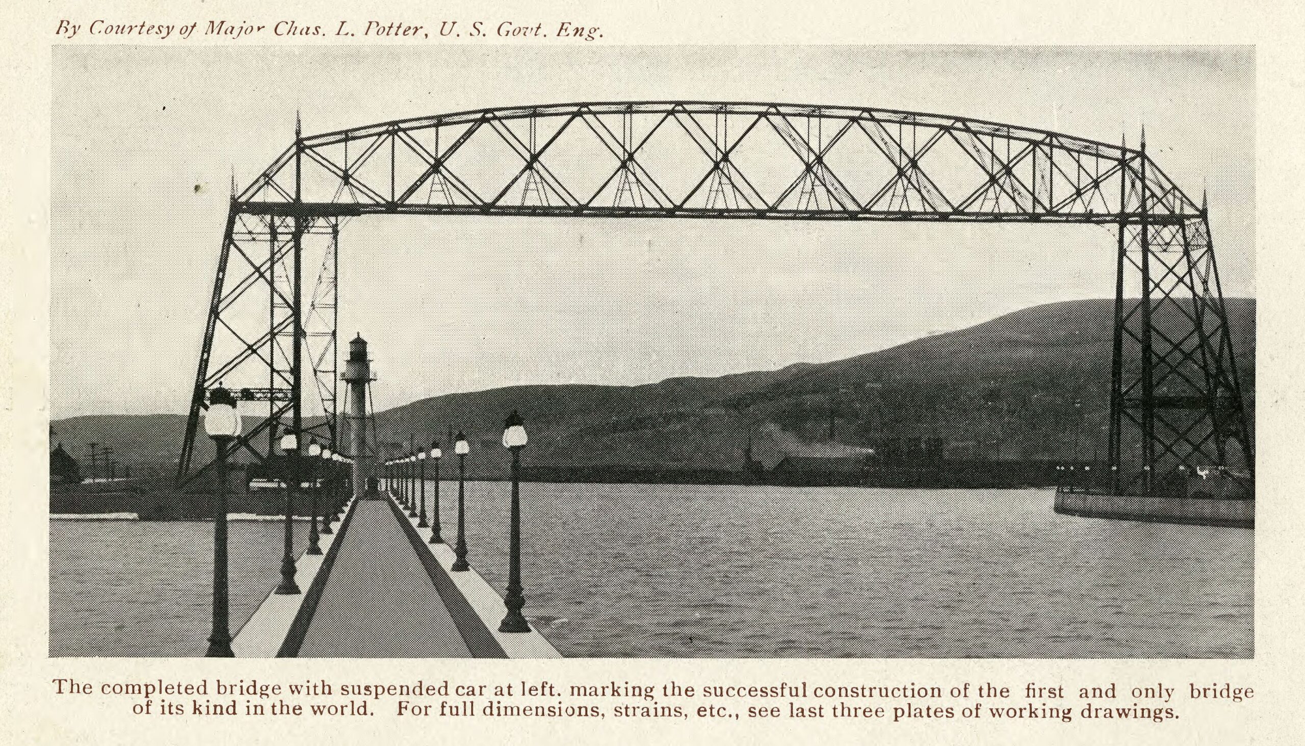
El puente finalmente construido tenía una altura libre, desde el nivel medio del Lago Superior, de 135 pies (41,15 m), que permitía el paso de los mástiles más altos. La viga metálica medía en el punto central 51 pies, por lo que la altura total era de 186 pies (56,70 m). La luz libre del puente era de 393,75 pies (120 m).
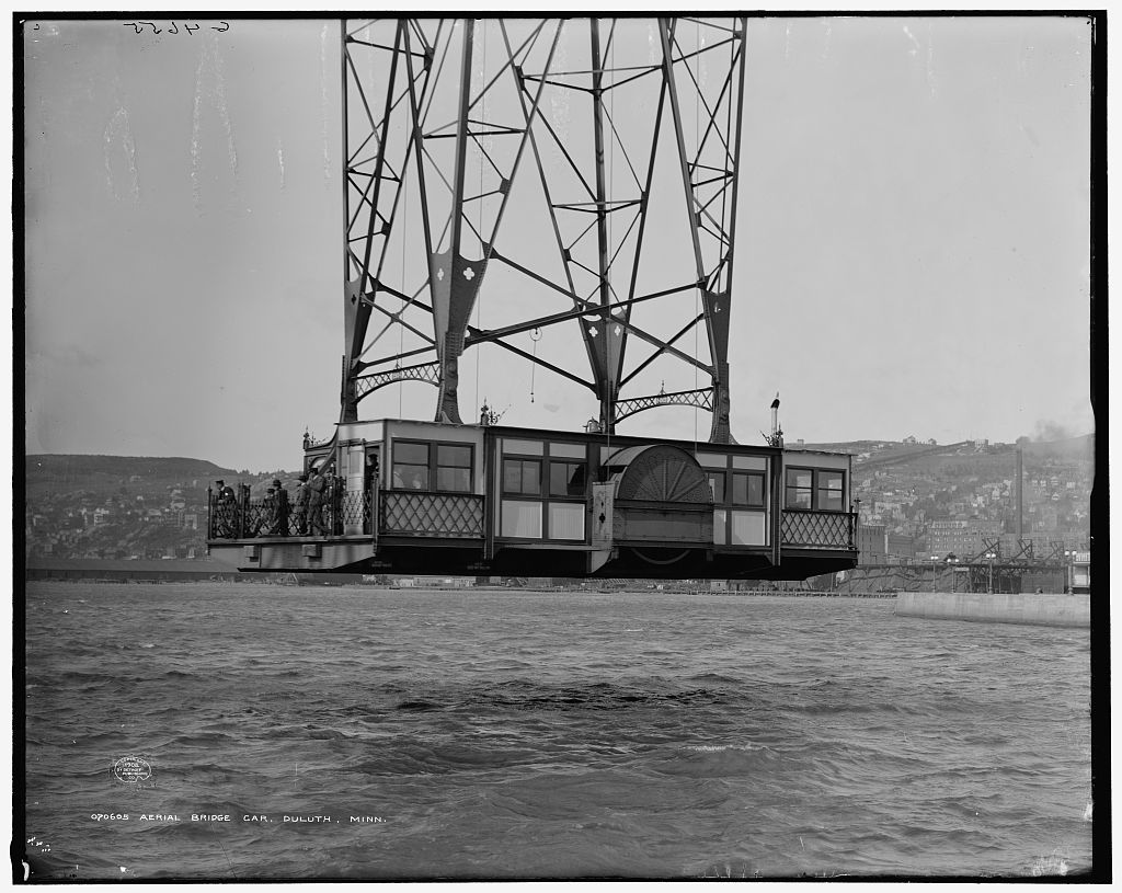
Barquilla del puente transbordador de Duluth, 1908. / Library of Congress. Estados Unidos.
Las dimensiones de la barquilla eran de 34 x 50 pies (10,35 x 15,25 m) y podía penetrar en tierra firme, por lo que no obstaculizaba el paso de buques cuando se encontraba parada. Estaba movida por medio de un motor eléctrico, duplicado por seguridad y podía accionarse también de modo manual en emergencias.
El puente se ha conocido como Aerial ferry bridge aunque también en ocasiones se le ha denominado Suspended car transfer bridge.
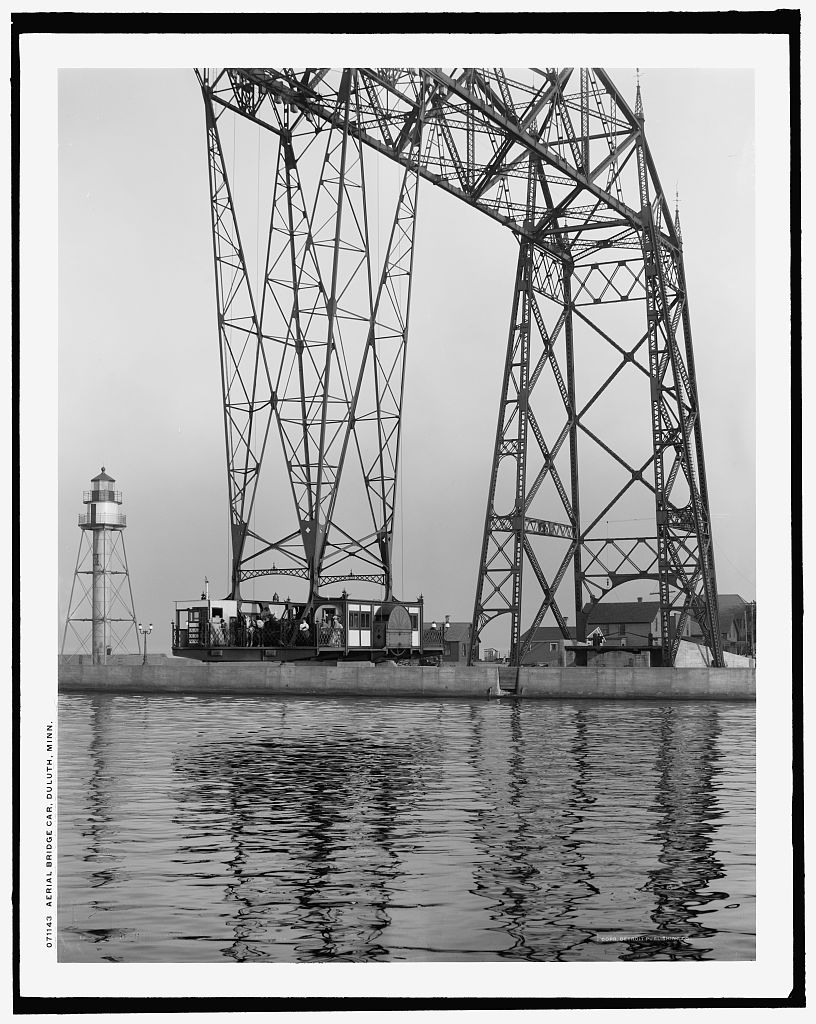
Puente transbordador de Duluth, 1908. / Library of Congress. Estados Unidos.
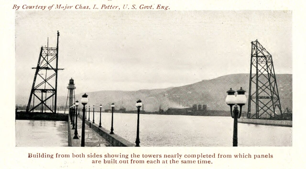
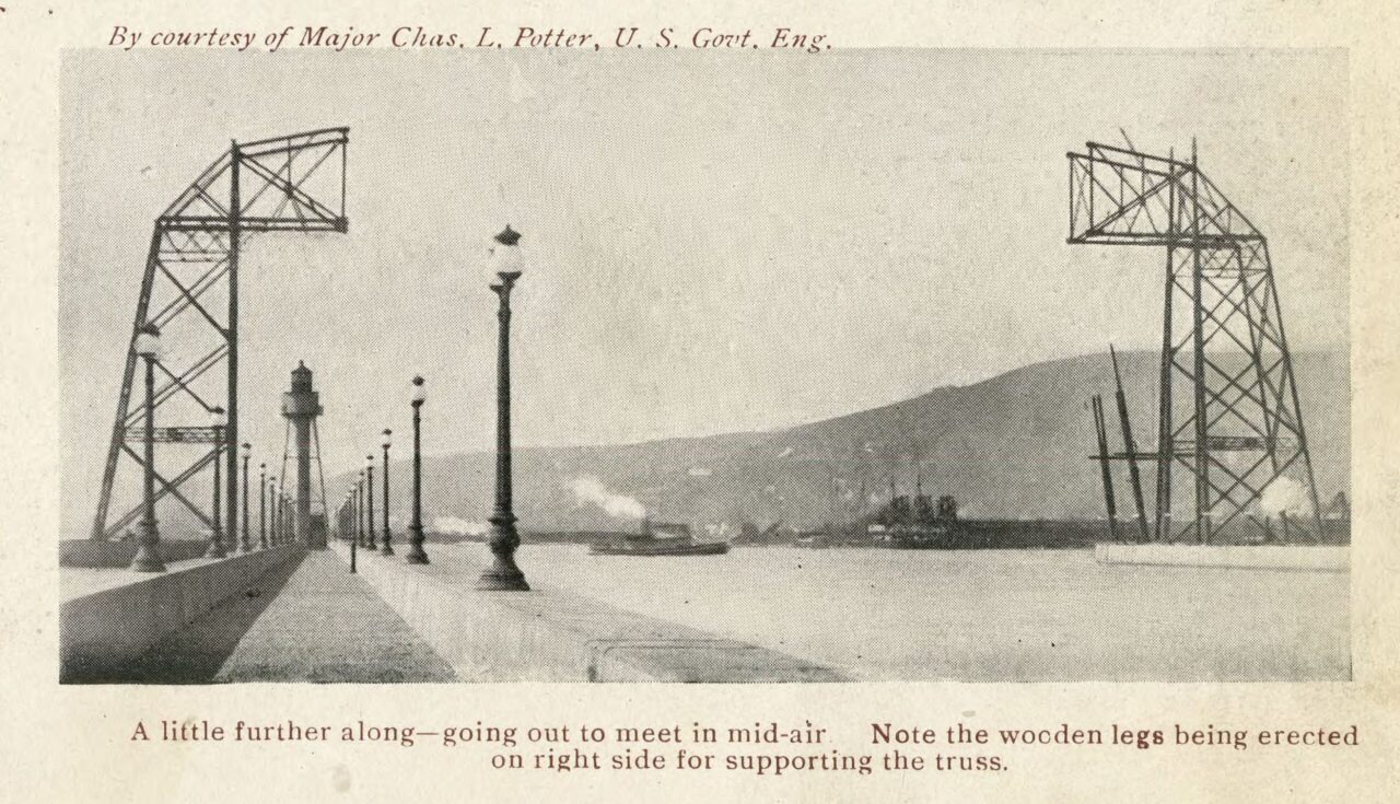
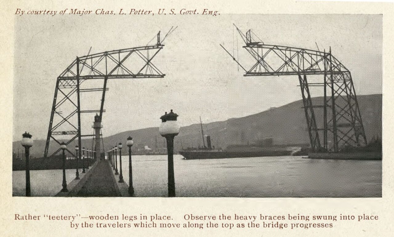
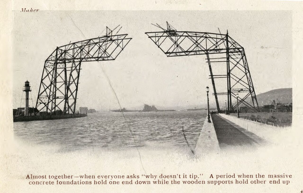
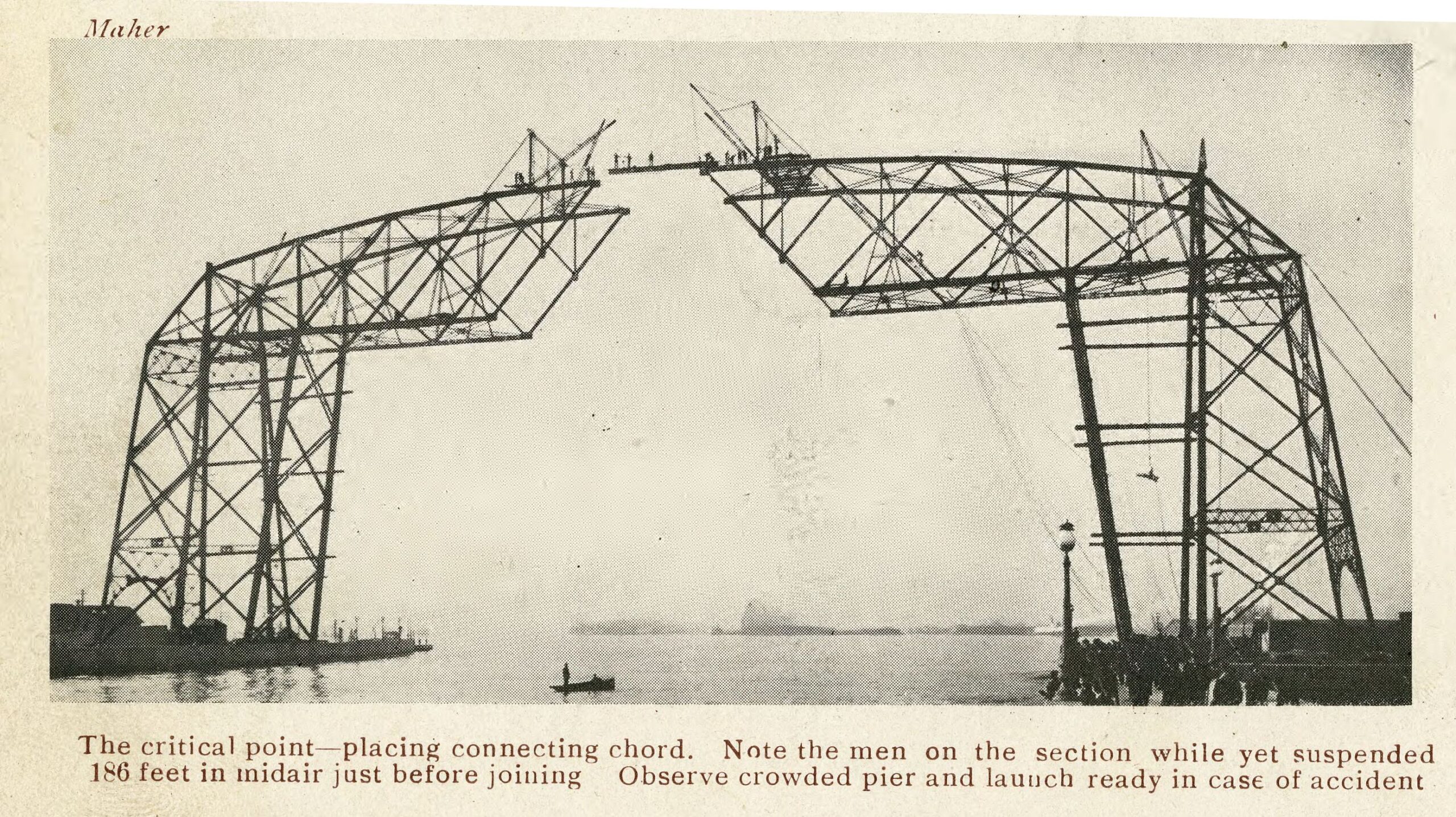
En 1905 el ingeniero Thomas F McGilvray, verdadero impulsor de la realización del puente, publicó un folleto en el que recogía los datos esenciales de la gestación de la idea y del proyecto, así como los datos técnicos de la obra de ingeniería; en el folleto se incluían fotografías de la progresión de los trabajos, fotografías que nos permiten contemplar el proceso constructivo de la viga por avance progresivo en voladizo (en cantilever) realizado desde las pilas ya construidas en las dos margenes del canal.
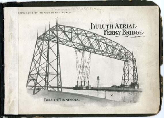
THE ONLY ONE OF ITS KIND IN THE WORLD
Duluth Aerial Ferry Bridge
DULUTH
THE ONLY ONE OF ITS KIND IN THE WORLD. Duluth Aerial Ferry Bridge, 1905 / Minnesota Digital Library.
Historical
The Duluth ship canal, through which passes annually the same commercial tonnage that is carried through the famous Suez canal, was cut across Minnesota Point by the City of Duluth in 1871, and pile and timber cribs to hold its banks were constructed the following year. This canal was later adopted by the U. S. Government, which in 1901 widened it from 240 feet to a least width of 300 feet, and constructed substantial and permanent piers of crib work and concrete. The opening of the canal converted Minnesota Point Make, into an island, and the city accepted the responsibility of providing the inhabitants with adequate communication with the main land. Until 1897 a row boat ferry was maintained, but as the population of the Point steadily increased, and it became popular for summer homes, a steam ferry for transportation of passengers and freight across the canal was in that year substituted tor the row boats, and has been in use ever since.
THE ONLY ONE OF ITS KIND IN THE WORLD. Duluth Aerial Ferry Bridge, 1905 / Minnesota Digital Library.
The Inception of the Project
The Aerial Bridge Scheme came about through the imperative necessity of better communication with the Point, at a less cost than was being paid for the steam ferry service. A tunnel was proposed but was abandoned on account of its prohibitory cost. A draw-bridge, a lift-bridge, a roller-bridge, were in turn proposed; but all failed to secure the necessary approval of the United States war department, whose requirements demanded a method of transportation which would in no way impede the traffic through the canal. The suspended car transfer bridge at Rouen, France, was brought to the attention of the city engineer in 1899, who prepared a plan adapting the general scheme to the conditions at the Duluth Ship Canal; the idea was favourably received by the U. S. War Department, and the people of Duluth; and a bond issue for the amount of the estimated cost of the structure ($100,000) was sanctioned by the State Legislature and a general specification and contract were prepared and let for the erection of the structure in 1901.
The concrete piers to sustain the bridge structure were built under the original contract, and the work was then abandoned by the contracting company. After various delays, a contract was finally entered into, in February, 1904, with the Modern Steel Structural Co., of Waukesha, Wis., for a riveted truss on riveted steel tower; the ferry car to be supported by an inverted steel tower, in accordance with designs submitted to the city engineer for approval by the Structural Company, made by their engineer, Mr. C. A. P. Turner. The work was erected and completed during the winter of 1904-5.
THE ONLY ONE OF ITS KIND IN THE WORLD. Duluth Aerial Ferry Bridge, 1905 / Minnesota Digital Library.
The Bridge
Foundations
In the foundations of the bridge there are 730 tons of concrete, in the 8 piers which extend be1ow the water level of the lake; 24 anchor bolts 2 inches in diameter, fastenened by means of large washers to the bottom of the piers hold the towers in position.
Loads
The car will carry at one time 125,000 lbs, which is equivelant to a fully loaded double-truck street car, two loaded wagons with teams and 350 passengers.
THE ONLY ONE OF ITS KIND IN THE WORLD. Duluth Aerial Ferry Bridge, 1905 / Minnesota Digital Library.
Dimensions
The bridge has a clear height, above the ordinary stage of Lake Superior, of 135 feet. This height was fixed by the Lake Carriers’ Association, and will permit of the passage of the highest masts. The truss at the center is 51 feet, making the total height of the highest part of the bridge above the water 186 feet. The width, center to center, of trusses, is 34 feet and the clear span is 393.75 feet.
The car platform is 34×50 feet and contains, in addition to space for a street car and two wagons, two enclosed and glazed cabins, of pleasing interior finish, each 7×30 feet. The elevation of the bottom of the car above the U. S. Government piers is 6 feet, and when the car is at rest, its whole length is over land; hence it is in no way an obstruction or menace to navigation. 700 tons of steel and over 100,000 rivets was used in the construction of the bridge.
THE ONLY ONE OF ITS KIND IN THE WORLD. Duluth Aerial Ferry Bridge, 1905 / Minnesota Digital Library.
Motive Power
The motive power of the ferry car is electricity, current being supplied from two separate sources, having different cable systems, and a switch under the control of the motorman, enables him in case of the failure of one source, to immediately turn on power from the other. A further safeguard against delays is provided by an adequate hand power, which can be used in the event of both sources of power failing.
Rate of Speed
The normal speed of the car is an average of four miles per hour, but the electrical machinery is capable of propelling the car at twice that speed. The passage across the canal is thus made in a little over one minute.
THE ONLY ONE OF ITS KIND IN THE WORLD. Duluth Aerial Ferry Bridge, 1905 / Minnesota Digital Library.
Machinery, Etc.
Two 40 H. P. motors, placed under the floor of the car, actuate two drums, each 9 feet in diameter, on which are wound one-inch cables extending to the truss, and thence over 9 foot idle-wheels, through the inside of the lower chords to the towers, where they are fastened, producing the motion which causes the car to run. The track, to carry the car and hangers, is ingeniously arranged, being enclosed on three sides within the box section of the lower chord, thus avoiding the danger of its becoming coated with snow or sleet in the winter time. There are four rails, within the two bottom chords, two in each, and 32 wheels, arranged in pairs (8 pairs in each lower chord) roll on them, which carry the truck. As the bearings of these wheels, as well as those of the drums and idlers, have roller ball end thrust bearing, the friction of all the working machinery is reduced to a minimum. The hand power method of propulsion is applied by use of lever handles, which, by a series of gears and sprocket/ communicate power to the drums on the car.
THE ONLY ONE OF ITS KIND IN THE WORLD. Duluth Aerial Ferry Bridge, 1905 / Minnesota Digital Library.
Cost
The cost of the steam ferry boat service averaged $11,000 per annum. The cost of the Ferry Bridge will be $8,000, which includes operation, maintenance and the interest on the bonds issued for the construction of the bridge. A sinking fund of $3,000 for the payment of the bond issue can thus be created, which will in time pay for the bridge.
The especial fitness of this type of bridge to existing conditions will doubtless be more fully appreciated when it is known what enoimious traffic passes under it. The following is an extract from a statement of Marine Commerce for the calendar year 1904, issued by Chas. L. Potter, Major, corps of U. S. Engineers, in charge of the Duluth-Superior harbor improvements—Tons passing through Duluth Ship Canal 4,037,608 entered; 7,113,297 departed — Total 11,150,- 905 passed through. Vessels entering 3,426; departing 3,147—total 6,573. Navigation season 217 days, year 1904—
«Considering the mean monthly freight movement during the season of navigation the Duluth-Superior harbor practically stands next to New York.»
The work of erection was immediately superintended by E. K, Coe, C. E., under the supervision of the City Engineer.
On April 9, 1905, 33,000 passengers were handled, of which 29,500 were between noon and 7:15 p. m. or practically one half day—7,781 in one hour and 814 on one trip.
Power necessary on average trip 18 H. P.
Car operates as well when wind blows 60 miles per hour as when no wind is blowing.
THOS. F. McGILVRAY,
Mem. Am. Soc. C. E.
City Engineer of Duluth
THE ONLY ONE OF ITS KIND IN THE WORLD. Duluth Aerial Ferry Bridge, 1905 / Minnesota Digital Library.
ARCHIVO:
.- El puente transbordador de Duluth. 1/ Arnodin en América
.- El puente transbordador de Duluth. 2/ La patente de Palacio y Arnodin en EE. UU.
.

María Isabel
¡Qué interesante!